
Maintenance Ajax Engine | Clearence and Torque

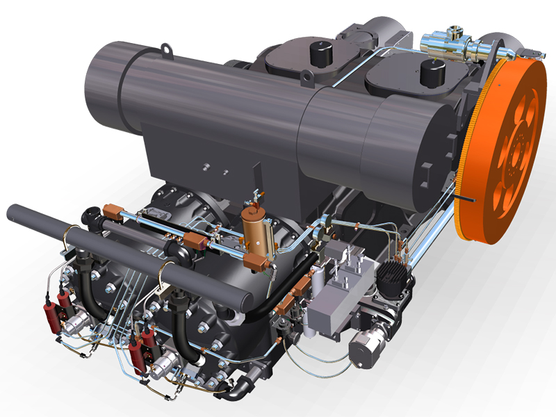
  Hallo teman - teman dhevils mechanic, ketemu lagi dengan tulisan - tulisan dhevils mechanic ya ng pasti tak jauh dengan dunia mechanic Oil and Gas Industry. Dimana sering kita ulas terkiat spec suatu peralatan, troubleshot, maupun ide - ide creative dalam menyeleseikan permasalahan yang terjadi di dunia mechanic. dan kali ini yuk kita berkisah terkait Ajax gas engine compressor, terkait clearence dan torque pada unit - unit ajax Untuk Perawatannya  unit ajx ini sangat simple karena selain mengadopsi model 2 stroke engine juga integral engine sehingga tidak banyak part yang digunakannya, untuk system instrumentasinya juga simple karena sebagian besar masih mengunakan type peneumatic control system. Nah sebagai seorang mechanic kita harus paham ukuran - ukuran clearance dan torque yang dibutuhkan pada setiap bagian - bagiannya, dan berikut ini coba kita share yang diambil dari berbagai sumber yang ada. CLEARANCE AND TORQUE VALUES (cont’d)  Description                                        DPC-300                                    DPC-360&2802 Clearances: Roller Main Bearing:  - Fit to Shaft (tight)                          002-.004 .                                       002-.004  - Bench Lateral (installed loose)     .0003-.0074                                    .0021-.0085  Center Main Bearing:                     .004-.007                                          .004-.007  Crankpin Bearing-Power                 .003-.006                                         .003-.006  - Side Clearance                            .010-.026                                           .010-.026  - Compressor                                  .003-.006                                           .003-.006  - Side Clearance                            .010-.026                                             .010-.026  Crosshead Pin Bearing-Power      .0044-.0074                                         .0044-.0074  - Compressor                                .003-.006                                              .0035-.0055  Crosshead to Guide-Power           .008-.012                                               .009-.015  - Compressor                                .012-.015                                               .012-.015  Piston to Power Cylinder:  - Skirt                                            .027-.033                                               .027-.033  - Below 3rd Comp. Ring               .067-.076                                               .067-.076  - 3rd Ring Land                             .142-.151                                               .142-.151  - 2nd Ring Land                           .142-.151                                                .142-.151  - 1st Ring Land                              .152-.161                                              .152-.161  Piston Ring End Gap                    .115-.135                                               .115-.135  Piston Ring to Side of:  - 1st & 2nd Groove                      .010-.0125                                             .010-.0125  - All Other Grooves                    .008-.0105                                              .008-.0105  Piston Crown to Head  Gasket Surface (distance)              2.250”                                                    2.250”  Layshaft Drive Gear Backlash     .003-.005                                              .003-.005  Layshaft End Play                            .005                                                     .005  Mag Drive Shaft End Play          .003-.014                                                .003-.014  Governor Drive Shaft End Play   .003-.006                                               .003-.006  Flywheel Rim Runout  (external start)                                   .020                                                       .020  Mixer Manifold  (min. thickness after regrind)   - Old Style                                         4.425”                                               4.425”  - New Plate Style (square)                    .562” .                                       562” Torque Values  (ft. lbs. for lubricated threads):  Connecting Rod Bolts  - Power-End                                             650-700                                   650-700  - Compressor-End                                    650-700                                    650-700  Cylinder Heads Stud Nuts                           600                                           600  Piston Rod to Crosshead Nuts                    3200                                           3200  Crosshead Pin Lock Screws                         50                                               50  Piston Rod Lock Screws                               50                                              50  Flywheel Bolt and Nuts                                520                                          520  Cooler Drive Sheave Bolt/Nuts                     225                                            225  Power Cyl. to Frame Studs                            490                                              490  Main Bearing Support to Frame                    150                                              150  Center Main Cap Bolts                                    250-265                                 250-265  Center Main Carrier to Frame Bolts                95 95  Compressor Guide to Frame Studs               280-300                                    280-300   B. CLEARANCE AND TORQUE VALUES (cont’d)  Description                                                    DPC-600&2803                                  DPC-800&2804 Clearances: Main Bearing:                                                           .0046-.0076                                   .0046-.0076  Thrust Bearing Side Clearance                                  .008-.018                                           .008-.018  Crankpin Bearing-Power                                           .003-.006                                         .003-.006  - Side Clearance                                                         .010-.026                                              .010-.026  - Compressor                                                              .003-.006                                              .003-.006  - Side Clearance                                                         .022-.036                                                 .022-.036  Crosshead Pin Bearing-Power                                  .0044-.0074                                        .0044-.0074  - Compressor                                                             .0035-.0055                                   .0035-.0055  Crosshead to Guide-Power                                        .009-.013                                         .009-.015  - Compressor                                                                .012-.015                                         .012-.015  Piston to Power Cylinder:  - Skirt                                                                         .027-.033                                            .027-.033  - Below 3rd Comp. Ring                                           .077-.086                                             .077-.086  - 3rd Ring Land                                                         .142-.151                                           .142-.151  - 2nd Ring Land                                                        .142-.151                                            .142-.151  - 1st Ring Land                                                         .152-.161                                            .152-.161  Piston Ring End Gap                                                .115-.135                                            .115-.135  Piston Ring to Side of:  - 1st & 2nd Groove                                                 .010-.0125                                          .010-.0125  - All Other Grooves                                                .008-.0105                                          .008-.0105  Piston Crown to Head  Gasket Surface (distance)                                         2.250”                                                2.250”  Layshaft Drive Gear Backlash                                .003-.005                                          .003-.005  Layshaft End Play .005 .005  Mag Drive Shaft End Play                                     .003-.014                                           .003-.014  Governor Drive Shaft End Play                            .003-.006                                           .003-.006  Flywheel Rim Runout (external start)                    .020                                                      .020  Mixer Manifold (min. thickness after regrind:  - New Plate Style (square)                                     .562”                                                  .562” Torque Values (ft. lbs. for lubricated threads):  Connecting Rod Bolts  - Power-End                                                         650-700                                                 650-700  - Compressor-End                                                 650-700                                                 650-700  Frame Tie-Bar Bolts                                             260                                                         260  Main Cap Studs (in frame)                                     250                                                       250  Main Cap Nuts                                                      360                                                        360  Cylinder Heads Stud Nuts                                     600                                                        600  Piston Rod to Crosshead Nuts                                3200                                                    3200  Crosshead Pin Lock Screws                                     50                                                         50  Piston Rod Lock Screws                                          50                                                         50  Flywheel Bolt and Nuts (split style)                          520  Flywheel Bolts (Ringfeder)                                     185  Cooler Drive Sheave Bolt/Nuts.                              225  Cooler Drive Sheave (Ringfeder)                         185  Vibration Damper Bolts 225  Power Cyl. to Frame Studs                                     490                                                     490  Compressor Guide to Frame Studs                         280-300                                             280-300     C. Wear Limits 13-1/4” and 15” Bore Units ONLY  Description                                                    As New Limits                         Max. Acceptable Power-End  13-1/4” Cylinder Bore                                       13.247-13.251                      13.263, Max of .002 TIR  13-1/4” Piston Skirt Diameter                           13.220-13.222                                13.213  13-1/4” Piston-to-Cylinder Clearance                .025-.031                                       .045  13-1/4” Piston Ring 1 & 2 Side Clearance         .010-.0125                                     .015  13-1/4” Piston Ring 3 & 4 Side Clearance          .008-.0105                                     .013  13-1/4” Piston Ring End Gap                               .100-.126                                    .145  15” Cylinder Bore                                                14.997-15.001                   15.013, Max of .002 TIR  15” Piston Skirt Diameter                                     14.968-14.970                             14.961  15” Piston-to-Cylinder Clearance                         .027-.033                                     .045  15” Piston Ring 1 & 2 Side Clearance                 .010-.0125                                     .015  15” Piston Ring 3 & 4 Side Clearance                   .008-.0105                                 .013  15” Piston Ring End Gap                                     .115-.135                                     .145  Piston Rod O.D.                                                    2.497-2.500                                 2.495  Crosshead Guide                                                     12.000-12.002                             12.004  Crosshead O.D.                                                     11.987-11.989                             11.985  Crosshead-to-Guide Clearance                                 .009-.013                                     .016  Connecting Rod Pin Bushing I.D.                         5.5044-5.5069                             5.509  Connecting Rod Side Clearance                             .010-.026                                     .029  Crosshead Pin O.D.                                                 5.4995-5.500                         5.4985, Max .001 TIR  Crosshead-to-Pin Clearance                                        .0044-.0074                             .0085  Connecting Rod Bearing Bore                             7.503-7.505                             7.507, Max .001 TIR  Crank Pin O.D.                                                     7.499-7.500                             7.4975, Max .0015 TIR  Crank Pin-to-Bearing I.D. Clearance                            .0044-.006                                     .0075  Main Bearing Journal O.D.                                             8.374-8.375                                 8.3725  Main Bearing I.D.                                                         8.3796-8.3816                    8.3831, Max .002 TIR  Main Journal-to-Bearing I.D. Clearance                                .0046-.0076                         .0091  Main Bearing Thrust (600, 800, 2803 & 2804 only)             .010-.020                                 .022  Layshaft Bearing Bore                                                             1.502-1.503                         1.504  Layshaft O.D.                                                                         1.498-1.500                            1.497  Layshaft O.D.-to-Bearing Clearance                                     .002-.005                                 .007  Center Main Bearing I.D. (2 cyl units only)                             7.754-7.756                         7.757  Crankshaft Journal O.D. (2 cyl units only)                             7.749-7.750                             7.748  Center Main-to-Journal Clearance (2 cyl only)                     .004-.007                                 .0084 Note: Specific Unit Performance and Maintenance Requirements May Vary Based on Application Conditions and Maintenance Practices. These Component Dimensional Specifications and Wear Limits Should Be Used as a Guide for Maintenance Programs for Ajax Equipment  C. Wear Limits 13-1/4” and 15” Bore Units ONLY  Description                                                   As New Limits                               Max. Acceptable Compressor-End Piston Rod, 2-1/2”                                               2.497-2.500                             2.495  Piston Rod, 2-1/4”                                              2.249-2.250                             2.2455  Crosshead Guide                                               11.999-12.001                           12.008  Crosshead O.D.                                                 11.984-11.986                           11.982  Crosshead-to-Guide Clearance                          .011-.015                                   .018  Connecting Rod Pin Bushing I.D.                     4.5035-4.5062                           4.507  Crosshead Pin O.D.                                            4.4995-4.500                            4.4985  Crosshead-to-Pin Clearance                               .0044-.006                                .0066  Connecting Rod Bearing I.D.                            7.503-7.505 7                            .506  Crank Pin O.D.                                                    7.499-7.500                              7.498  Crank Pin-to-Bearing Clearance                      .0042-.0066                                 .008  Demikianlah terkait guiden dalam merawat unit gas engine kompressor merk ajax, semoga dapat membuka wawasan kita terkait dunia mechanic oil and gas.
http://dlvr.it/SZ0pxb